1. Introduction
A TFT display (Thin Film Transistor display) is a high-performance active matrix LCD widely used in industrial control, medical devices, automotive systems, and consumer electronics. Because each pixel is driven by individual transistors, testing is critical to ensure stability, brightness, and long-term reliability.
This guide provides a comprehensive, step-by-step testing procedure covering electrical, optical, environmental, and functional verification. It serves as a practical reference for engineers, quality inspectors, and manufacturers involved in TFT display evaluation.
2. Test Environment and Equipment Preparation
Before starting, ensure that the test conditions and tools meet industry standards.
2.1 Test Environment
Ambient temperature: 25 ± 5 °C
Humidity: 40–70% RH
Lighting: 6500 K daylight lamp for consistent observation
Cleanliness: Dust-free environment to prevent contamination during inspection
2.2 Test Equipment
| Equipment | Purpose |
| Pattern Generator | Provides standard RGB/gray test images |
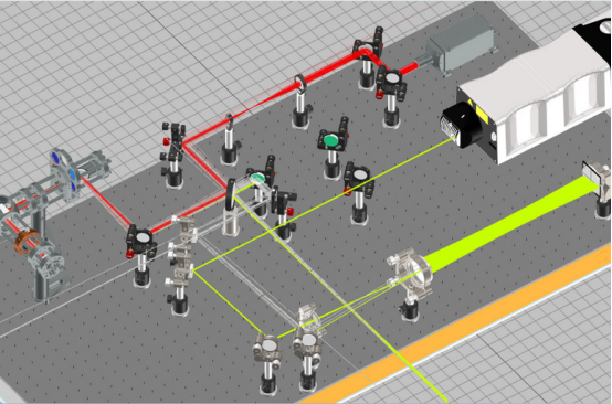
| Color Analyzer or Luminance Meter | Measures brightness, contrast, color gamut |
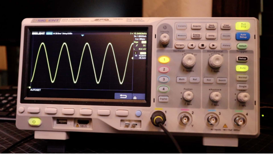
| Oscilloscope | Checks signal waveform and synchronization |
| Power Supply Unit | Provides stable DC input voltage |
| Temperature & Humidity Chamber | Simulates environmental reliability tests |
| Aging System | Runs long-duration operation for endurance evaluation |
3. Visual and Physical Inspection
3.1 Appearance Check
Inspect the TFT display under normal light before powering on:
Confirm that the surface is free from scratches, stains, or cracks.
Check that the FPC connector and backlight components are correctly mounted.
Examine for bubbles or delamination on the polarizer.
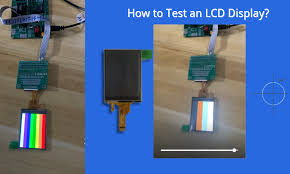
3.2 Dead Pixel Check
Display full-color test patterns (Red, Green, Blue, White, Black).
Defects are identified as:
Bright pixel: Always ON when showing black.
Dark pixel: Always OFF when showing white.
Standard tolerance: ≤ 3 dead pixels per display (based on ISO 9241-307).

4. Electrical Performance Testing
Electrical testing ensures that the display’s internal circuitry and driving IC function properly.
Operating voltage (VDD): Typically 3.0–3.3 V
Logic voltage (IOVDD): 1.8 V or 2.8 V depending on controller IC
Operating current: Must not exceed 5% deviation from specification
Signal timing: Verify HSYNC, VSYNC, and CLK frequencies using an oscilloscope
Backlight voltage and current: Check LED circuit for uniform brightness and correct current (e.g., 20 mA ± 1 mA per channel)
Abnormal readings may indicate soldering defects or driver IC damage.
5. Optical Performance Testing
5.1 Brightness and Contrast
Using a color analyzer positioned 30 cm from the screen center:
Brightness (Luminance): ≥ 500 cd/m² for outdoor displays; ≥ 300 cd/m² for indoor models
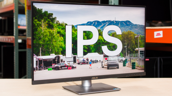
Contrast Ratio: ≥ 800:1 for standard modules, ≥ 1000:1 for IPS panels
5.2 Color and Viewing Angle
Color Gamut (NTSC): ≥ 70% for standard displays
Viewing Angle: Minimum 70° (horizontal and vertical) without color inversion
Test with 100% RGB color patterns and gray scale images.
5.3 Response Time
Measure transition from black-to-white-to-black:
Typical: ≤ 30 ms for TN type; ≤ 20 ms for IPS
Longer response times may cause ghosting or motion blur.
6. Uniformity and Mura Inspection
Uniformity reflects the evenness of backlight distribution.
Display a white test pattern and measure nine points across the screen.
Luminance uniformity = (Lmin / Lmax) × 100%
Acceptable value: ≥ 80%
Visually inspect mura (cloudy or uneven brightness). Any visible non-uniform region larger than 2% of screen area is considered a defect.
7. Environmental and Reliability Testing
Reliability testing ensures the TFT display performs under various environmental stresses.
| Test Item | Condition | Duration | Result Criteria |
| High Temp Storage | +80°C | 48 hours | No deformation, normal display |
| Low Temp Storage | –30°C | 48 hours | No leakage or display damage |
| Thermal Shock | –20°C ↔ +70°C | 10 cycles | No color shift or malfunction |
| High Temp / Humidity | 60°C, 90% RH | 96 hours | Contrast reduction <10% |
| Vibration | 10–55 Hz, 1.5 mm amplitude | 30 min/axis | No connector looseness |
| Drop Test | 1.0 m height | 1 time | No mechanical damage |
After each test, perform optical and electrical re-evaluation to confirm consistency.
8. Functional and Interface Verification
Connect the TFT display to the target control board via its communication interface:
RGB/LVDS/MIPI/SPI Interface Testing: Verify correct signal mapping and color order (e.g., RGB565 or RGB888).
Confirm refresh rate of 60–120 Hz for flicker-free display.
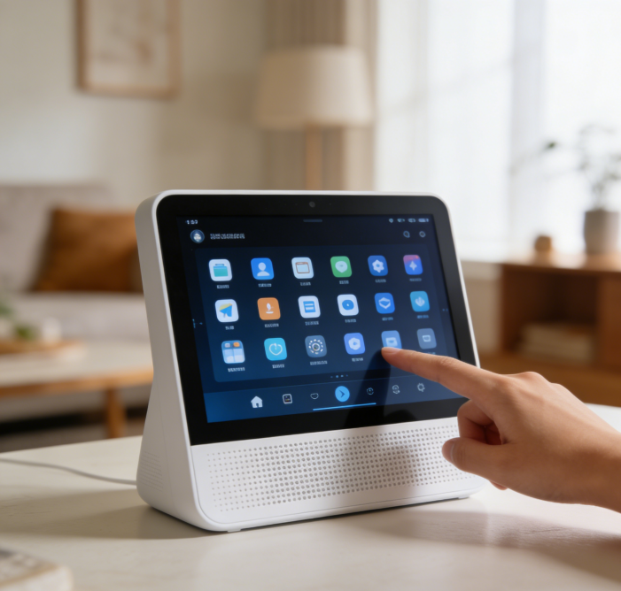
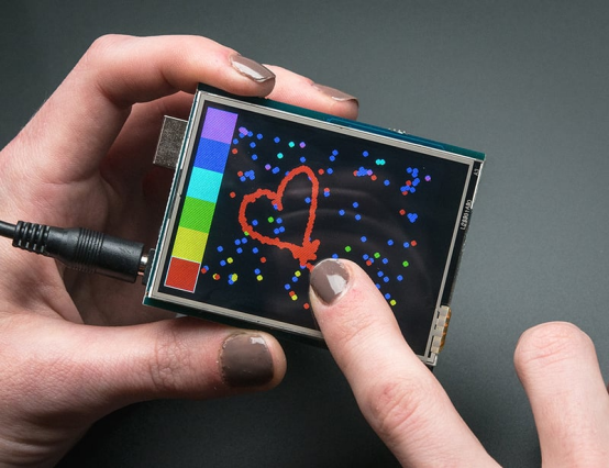
Touch Function (if integrated): Check accuracy, response speed (<50 ms), and multi-touch detection.
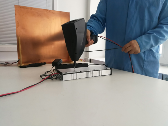
ESD Test: ±8 kV air discharge, no malfunction or flicker allowed.
9. Aging and Final Quality Assurance
Run the aging test continuously for 72 hours at 40°C to identify early failures.
Monitor brightness stability, color drift, and temperature rise in the LED backlight area.
Qualified products should maintain at least 95% of initial luminance after aging.
All test data must be documented in a Final Inspection Report, including:
Test conditions and instruments used
Measured values and limits
Pass/fail results with inspector signature
10. Conclusion
Testing a TFT display is a multi-step process involving optical, electrical, and environmental validation. A systematic approach not only guarantees product reliability but also minimizes failure rates in final applications.
At Shenzhen Easy Quick Technology Co., Ltd., each TFT module undergoes rigorous in-house testing under ISO quality standards. Our advanced optical equipment and automated inspection lines ensure stable brightness, precise color, and extended durability, making them ideal for industrial and outdoor environments.
Through consistent testing and continuous optimization, TFT display performance can be accurately guaranteed—ensuring every pixel delivers perfection.